

PV Input Voltage 20~60V AC Output 110V/230V Auto 600W/700W/800W/1000W Micro Solar Grid Tie Inverter With WIFI Monitor
SG-800W-WIFI / 80-280V / China Mainland|20-60V
₱11,168.92PHP
Sale price
₱11,168.92PHP
Regular price
Skip to product information


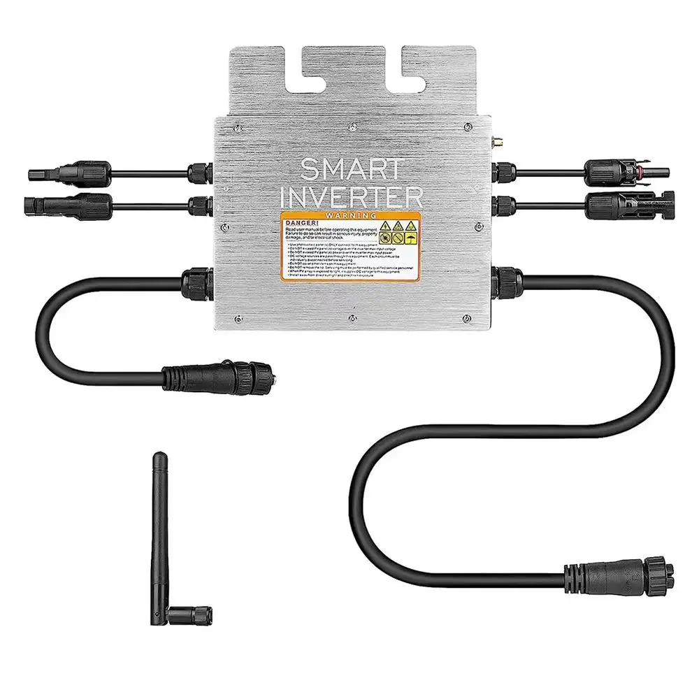


PV Input Voltage 20~60V AC Output 110V/230V Auto 600W/700W/800W/1000W Micro Solar Grid Tie Inverter With WIFI Monitor
₱11,168.92PHP
Sale price
₱11,168.92PHP
Regular price
Pickup currently not available
SPECIFICATIONS
Brand Name: NONE
Certification: CE,RoHS
EU LVD Voltage: High voltage: Above 50Vac or 75Vdc
High-concerned chemical: None
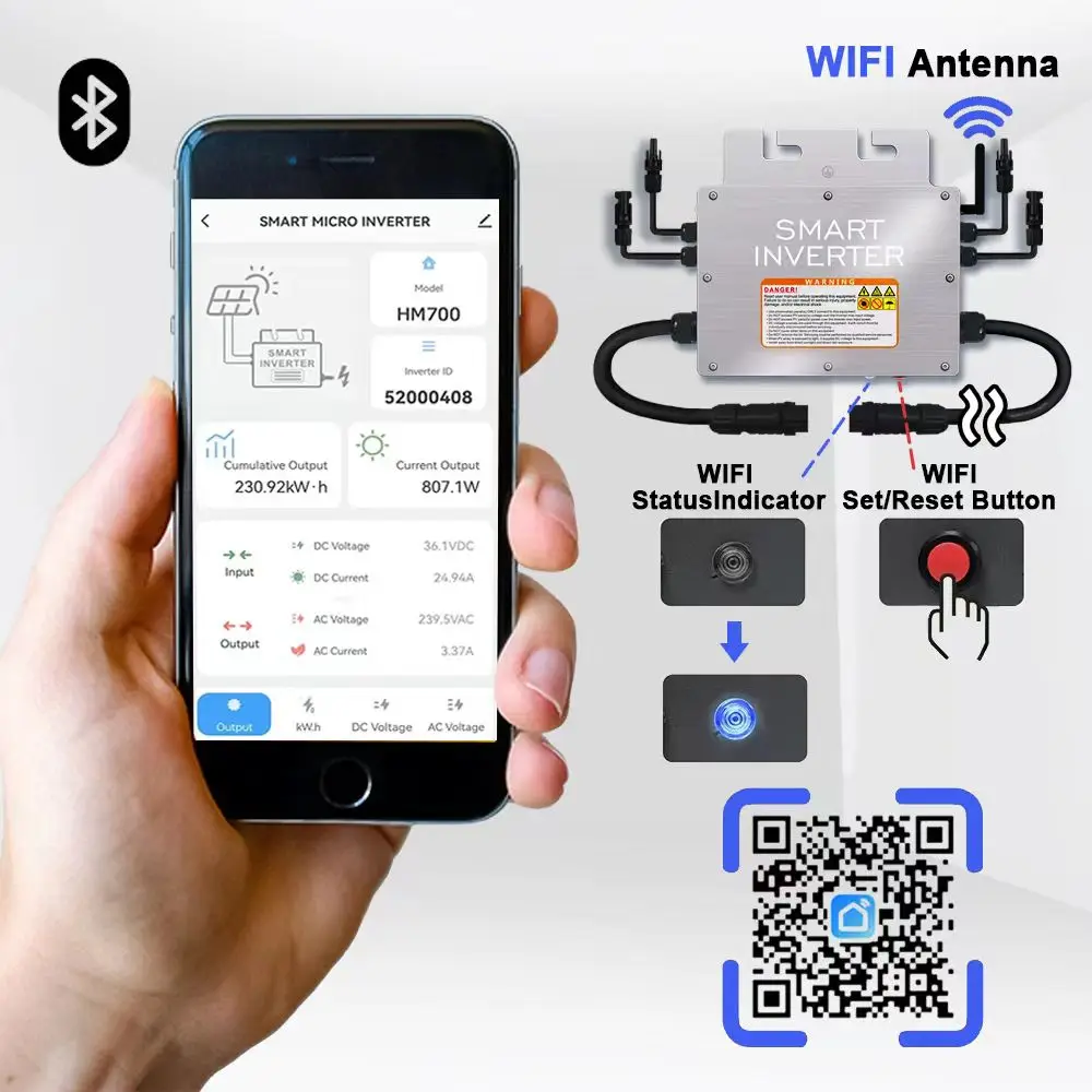
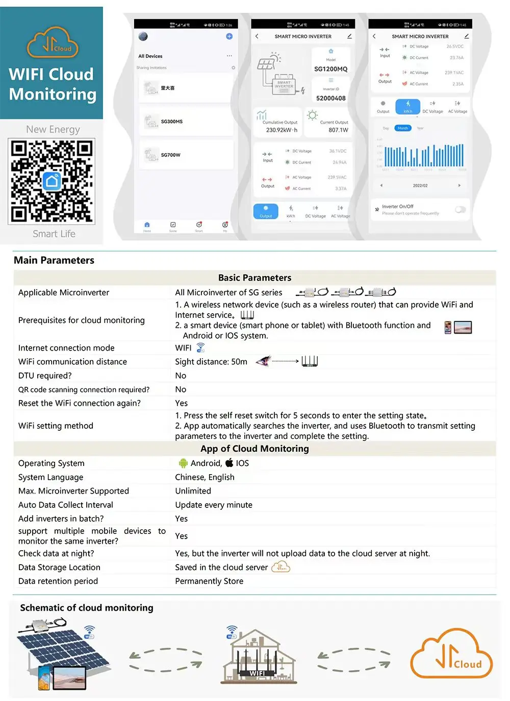
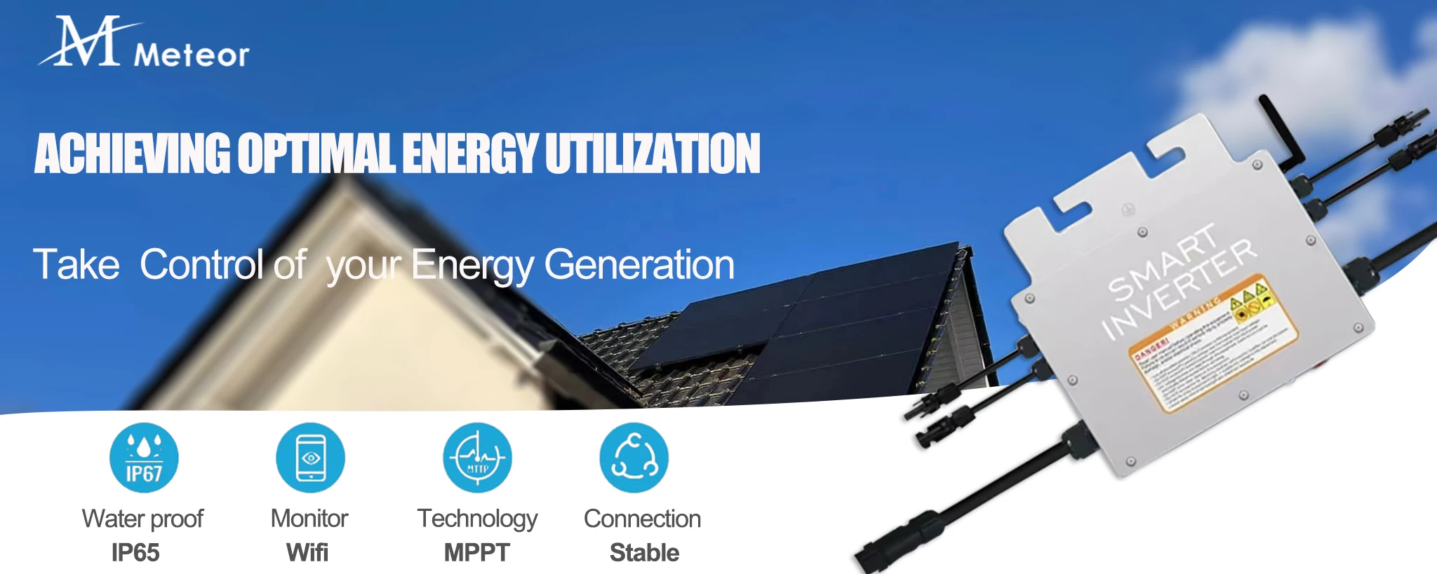
Is Smart Device: Yes
Origin: Mainland China
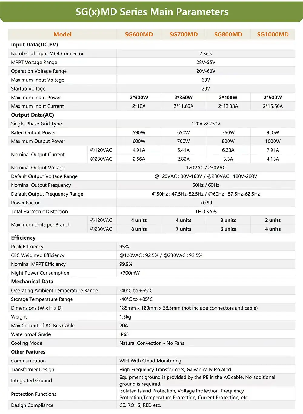
Output Frequency: 50/60hz
Output Voltage: 120V/230V
Power: 600/700/800/1000W
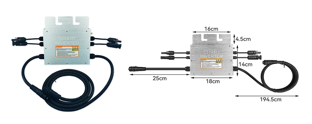
Size: 185mm x 180mm x 38.5mm
Weight: 1.5kg

 WARNING! DANGER!
Read user manual before operating this equipment. Failure to do so can result in serious injury, property damage,
and/or electrical shock.
• Use photovoltaic panel(s) ONLY connect to this equipment.
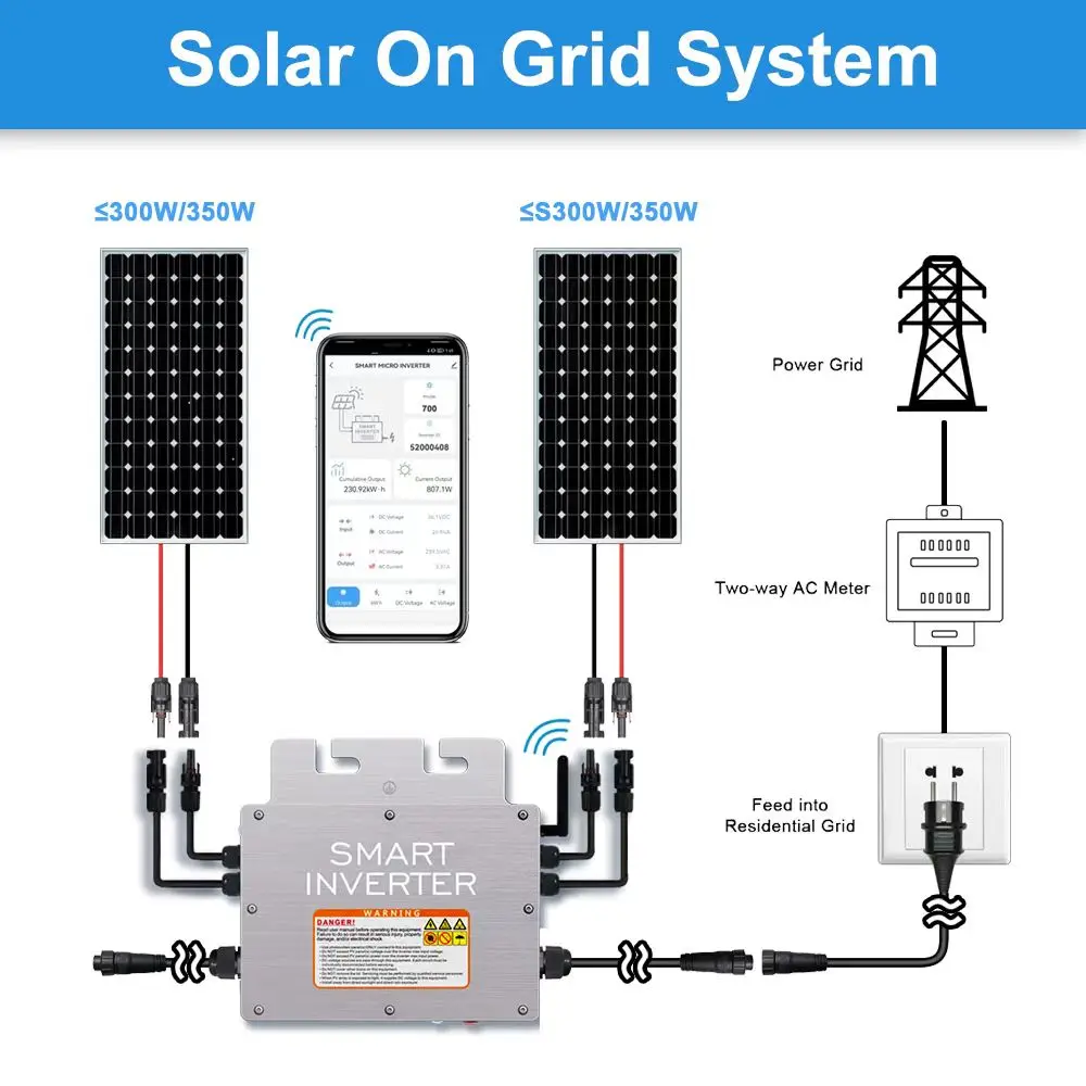
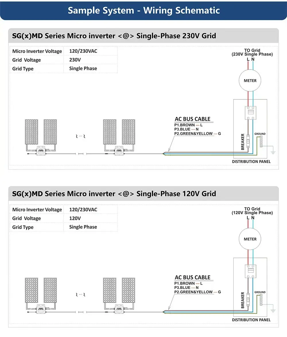
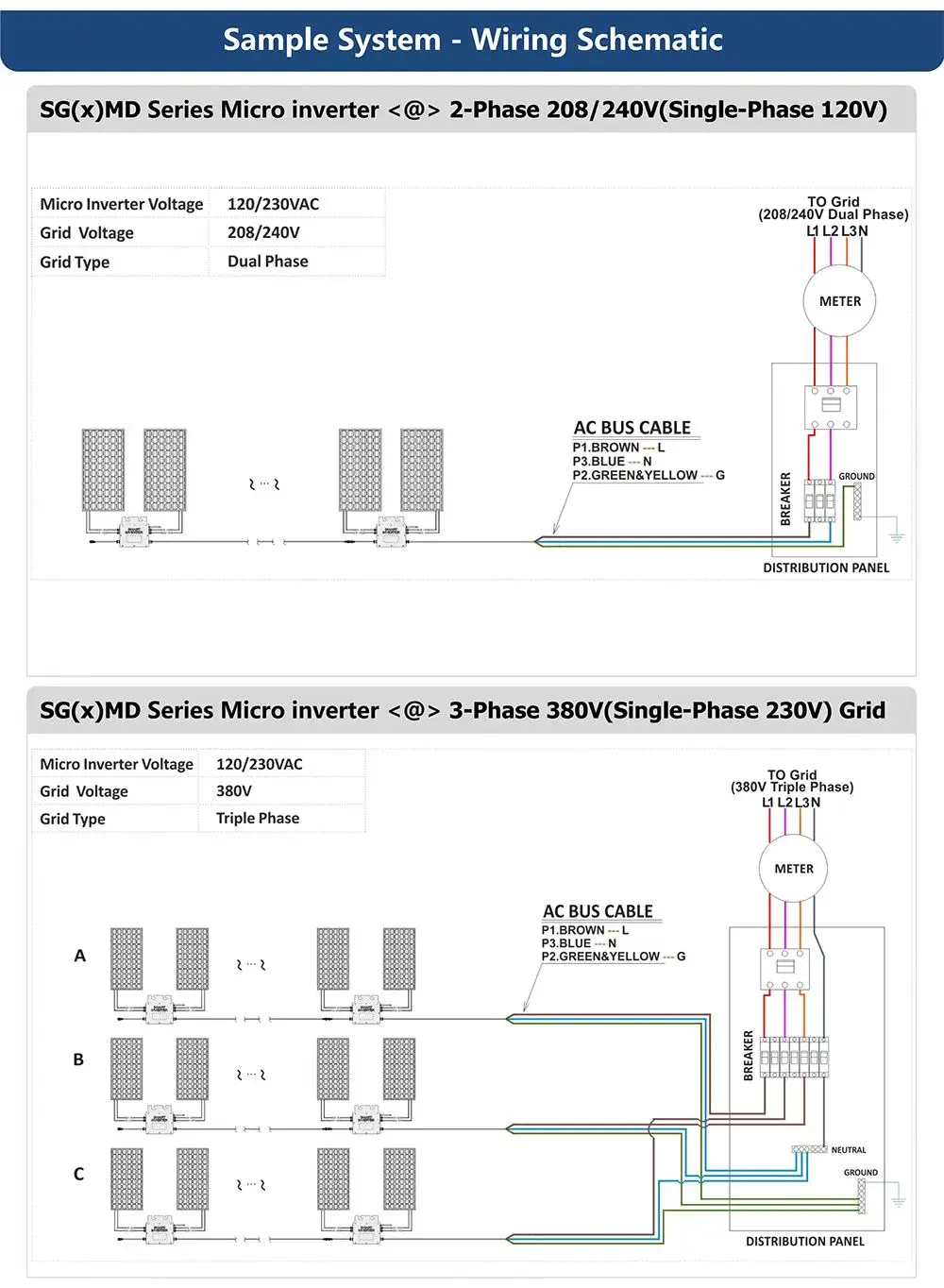
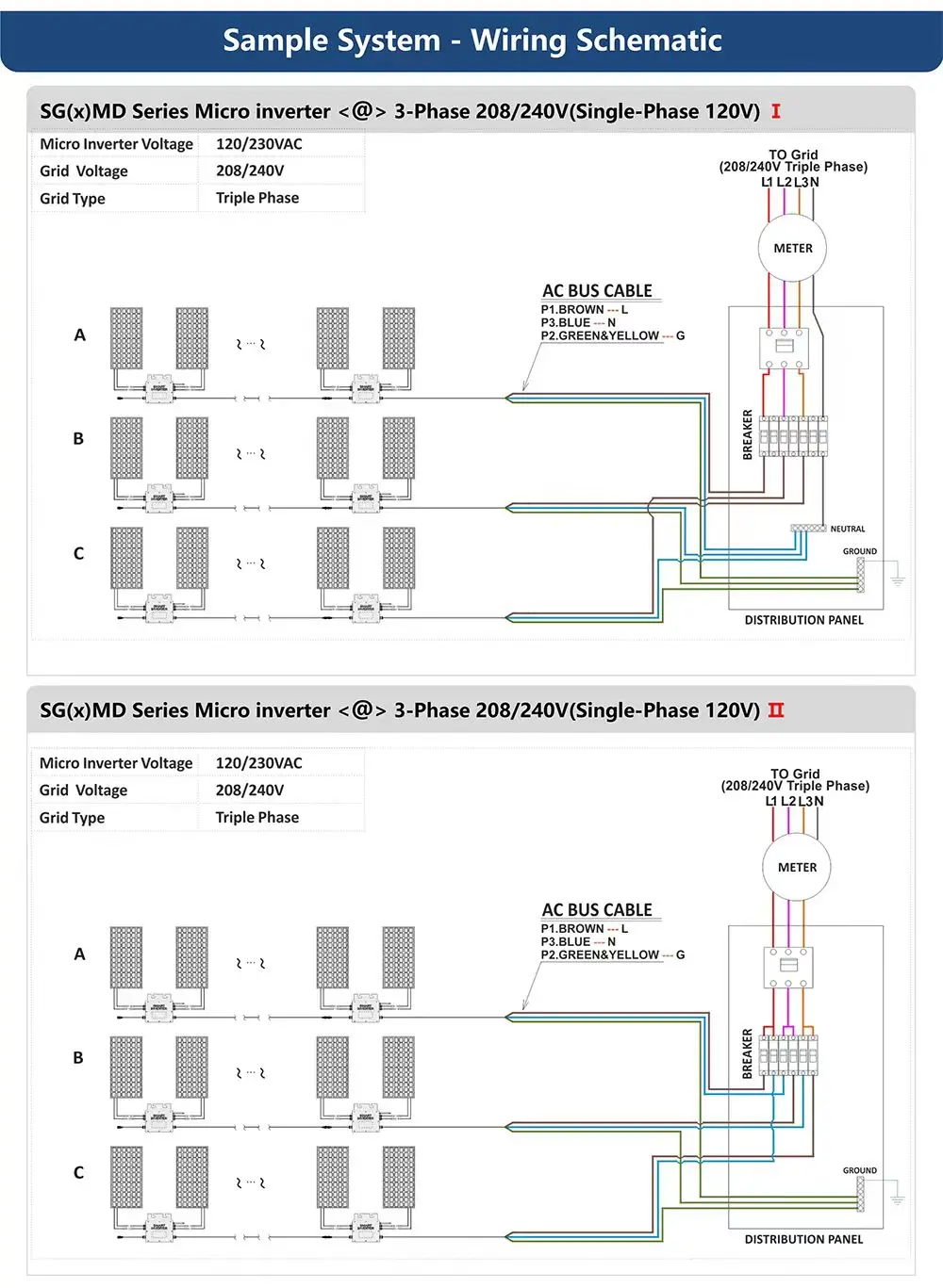
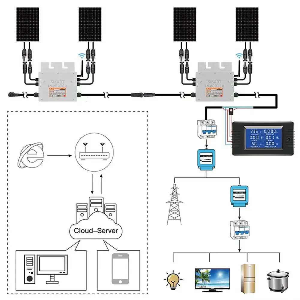
• This equipment is ON-GRID Microinverter, To make it work properly, it must be connected to the power grid correctly,
and the power grid is working properly, When the power grid stopped working, it will also stop generating.
• Do NOT exceed PV panel(s) voltage over the inverter max input voltage.
• Do NOT exceed PV panel(s) power over the inverter max input power.
• DC voltage sources are pass through this equipment. Each circuit must be individually disconnected before servicing.
• Do NOT cover other items on this equipment.
• Do NOT remove the lid. Servicing must be performed by qualifified service personnel.
• When PV array is exposed to light, it supples DC voltage to this equipment.
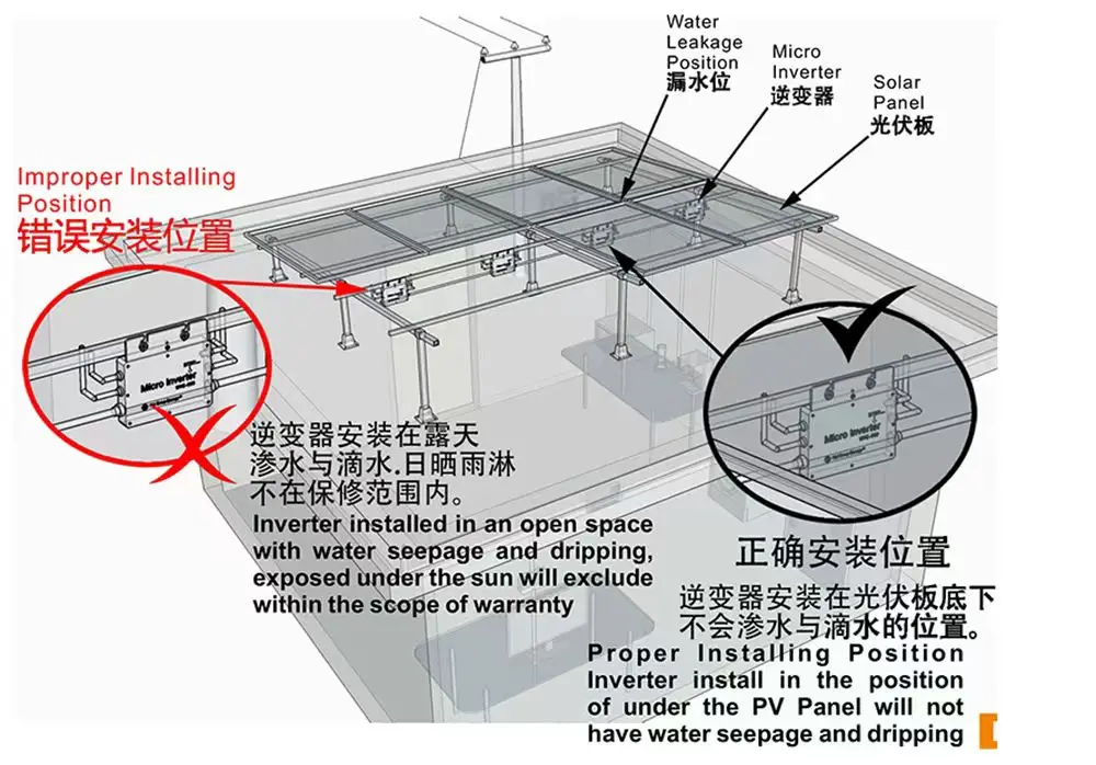
• Install away from direct sunlight and direct rain exposure.
LED DISPLAY
1.Green light steady
=Microinverter in generating.
2. Red flash
=Micro inverter in waiting.
3.Red light steady
=
a. Island protection.
b.Over-temperature protection.
c.Over / low AC voltage protection.
d.Over / low DC voltage protection.
e.Over / low AC frequency protection.
f.Fault.
INSTALLATION PROCEDURES
Step 1 -
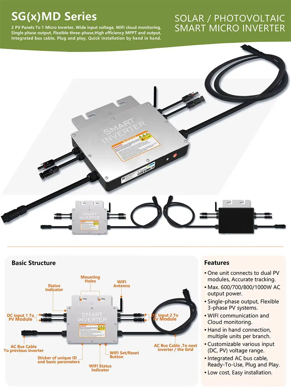
Attaching the Micro inverters to the Racking. a. Mark the location of the Micro inverter on the rack, with respect to the PV module junction box or any other obstructions. b. Mount one Micro inverter at each of these locations using hardware recommended by your module racking vendor.
Step 2 -
Connecting the Micro inverter AC bus cable one by one, Please do NOT exceed the Maximum Units per Branch.
Step 3 -
Connecting Micro inverters to the PV Module. Please do NOT exceed PV panel(s) VOC over inverter max. input voltage.
Step 4 -
Tighten the Bus Cable End Cap at the end of AC bus cable.
Step 5 -
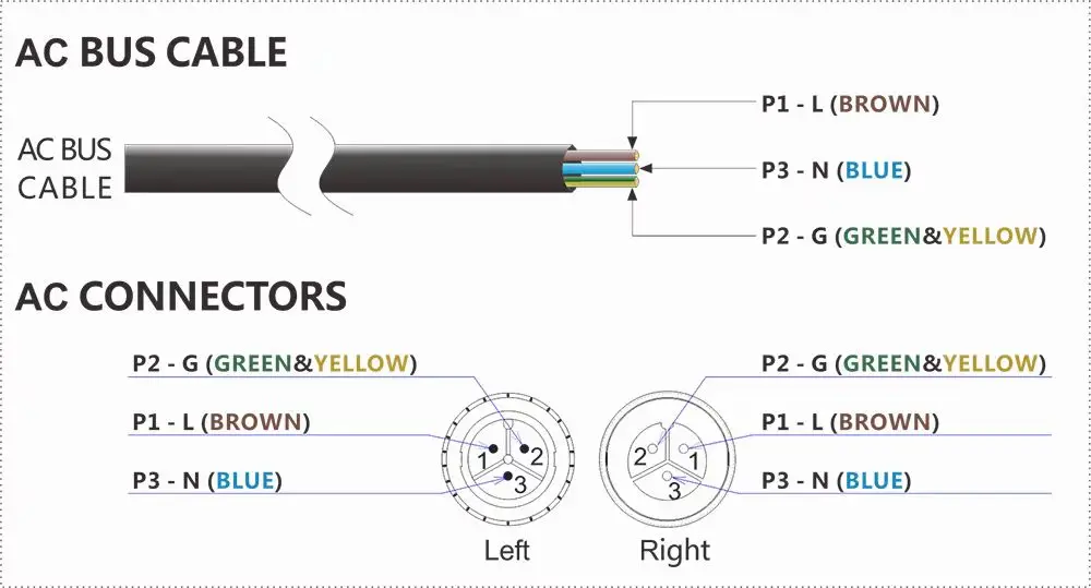
Install the AC Branch Circuit Junction Box, Wire the conductors of the AC bus cable: L-BROWN,N-BLUE,G-GREEN&YELLOW. Connect the AC branch circuit junction box to the point of utility-grid Interconnection.
Step 6 -
Double check all Micro inverters, connectors and cables are correctly and well connected.
Step 7 -
Turn ON the AC circuit breaker on each AC branch circuit of Micro inverter.
Step 8 -
Turn ON the main AC circuit breaker of utility-grid. Your system will start producing power after a 30sec safety delay period.